Solenoid Bumper
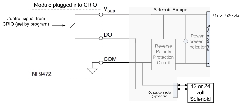
The solenoid valves generally used for FRC are 12 or 24 volt units rated about about one watt, which translates to .083 amps for 12 volts and .042 amps for 24 volts. This is not enough current to justify using the spike relays we use for single speed motor controls, but it is too much current for low current logic outputs, and the wrong voltage. To drive these devices, FIRST supplies a switch module for the CRIO that is capable of providing .75 amps switched from an external power supply. This module (NI9472) is a switching device that completes a connection from the power supplied through the solenoid bumper to an output that corresponds to a switching signal that comes from the CRIO under program control. This switching signal responds to your program telling a specific solenoid valve to open or close. The switching action is illustrated in the schematic below.
The switch symbol represents electronics in the NI9472 module that connects the power input to an output pin of the module. As shown in the schematic, the FIRST solenoid bumper that plugs into the module performs three functions:
- Provides a connection to a power supply (12 or 24 volts).
- Provides a more convenient connection point for wiring to individual solenoids.
- Protects the module from accidentally connecting the power in reverse.
- Provides an indicator light to show that power is being supplied to the module
Click here for information at WPI.
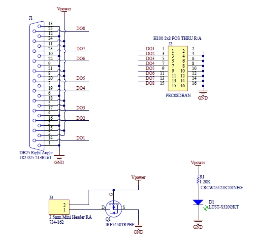
The detailed WPI schematic of the solenoid bumper, cut and pasted from the FRC web site, is shown below. The reverse voltage protector is a field effect transistor that connects the ground line only if the gate electrode is positive relative to ground.

