Difference between revisions of "Analog Bumper"
| (3 intermediate revisions by the same user not shown) | |||
| Line 1: | Line 1: | ||
<div style="text-align: right;"> | <div style="text-align: right;"> | ||
| − | [[CRIO Interfaces|'''Back to | + | [[CRIO Interfaces|'''Back to cRIO Interfaces''']] |
</div> | </div> | ||
| − | For connecting to analog sensors, FIRST provides the NI9201 analog input module plug-in for the CRIO. This module has eight analog inputs that can be read by the robot program. To make it easier to interface with this module, the FRC Analog Bumper (AKA Analog Breakout) is provided, which plugs into the DB25 connector on the NI9201 module. Because FRC sensors typically operate with a 5 volt power supply, the Analog Bumper includes a clean 5 volt DC to DC converter | + | For connecting to analog sensors, FIRST provides the NI9201 analog input module plug-in for the CRIO. This module has eight analog inputs that can be read by the robot program. To make it easier to interface with this module, the FRC Analog Bumper (AKA Analog Breakout) is provided, which plugs into the DB25 connector on the NI9201 module. Because FRC sensors typically operate with a 5 volt power supply, the Analog Bumper includes a clean 5 volt DC to DC converter. |
[[File:Analog-bumper-ckt.jpg]] | [[File:Analog-bumper-ckt.jpg]] | ||
| + | |||
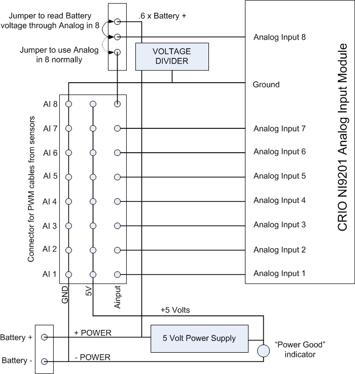
| + | This block diagram shows how the parts of the analog bumper are connected. The three-wire PWM cables carry power and ground to each sensor to provide power for its circuitry, and the sensor's analog value back to the cRIO's analog input module. The reason for having a power supply on this breakout is to make sure the sensors get clean and quiet power that is private to the sensors (not being used by other robot circuits that could introduce electrical noise.) The voltage divider that optionally drives analog input 8 is there because the analog input module only works up to 10 volts. The voltage divider multiplies the 12 volt battery voltage by a factor of .6 before feeding it to the analog interface, and the software restores it to the correct value. The capacitor in the voltage divider circuit works with the input resistor to filter out noise on the battery line. The jumper that selects between this reduced battery reading and the eighth sensor input can be used in cases where there is a second analog input module. | ||
| + | |||
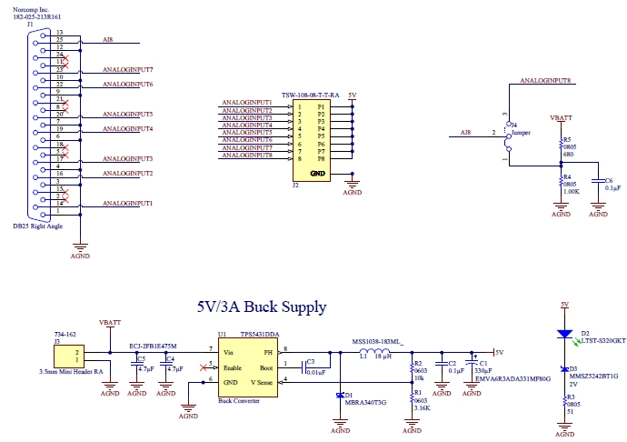
| + | The actual detailed WPI schematic of the Analog Bumper, cut and pasted from the FRC web site, is shown below. The local power supply is called a Buck Supply because it is implemented as a specific type of switching DC to DC converter. The voltage divider includes a filter capacitor to filter out most of the high frequency noise on the battery supply so that the analog input gets a consistent snapshot of the average battery voltage. | ||
| + | |||
| + | [[File:Analog-bumper-schematic.jpg]] | ||
Latest revision as of 23:34, 15 January 2014
For connecting to analog sensors, FIRST provides the NI9201 analog input module plug-in for the CRIO. This module has eight analog inputs that can be read by the robot program. To make it easier to interface with this module, the FRC Analog Bumper (AKA Analog Breakout) is provided, which plugs into the DB25 connector on the NI9201 module. Because FRC sensors typically operate with a 5 volt power supply, the Analog Bumper includes a clean 5 volt DC to DC converter.
This block diagram shows how the parts of the analog bumper are connected. The three-wire PWM cables carry power and ground to each sensor to provide power for its circuitry, and the sensor's analog value back to the cRIO's analog input module. The reason for having a power supply on this breakout is to make sure the sensors get clean and quiet power that is private to the sensors (not being used by other robot circuits that could introduce electrical noise.) The voltage divider that optionally drives analog input 8 is there because the analog input module only works up to 10 volts. The voltage divider multiplies the 12 volt battery voltage by a factor of .6 before feeding it to the analog interface, and the software restores it to the correct value. The capacitor in the voltage divider circuit works with the input resistor to filter out noise on the battery line. The jumper that selects between this reduced battery reading and the eighth sensor input can be used in cases where there is a second analog input module.
The actual detailed WPI schematic of the Analog Bumper, cut and pasted from the FRC web site, is shown below. The local power supply is called a Buck Supply because it is implemented as a specific type of switching DC to DC converter. The voltage divider includes a filter capacitor to filter out most of the high frequency noise on the battery supply so that the analog input gets a consistent snapshot of the average battery voltage.

