Power Distribution Module
From Ed's Mediawiki
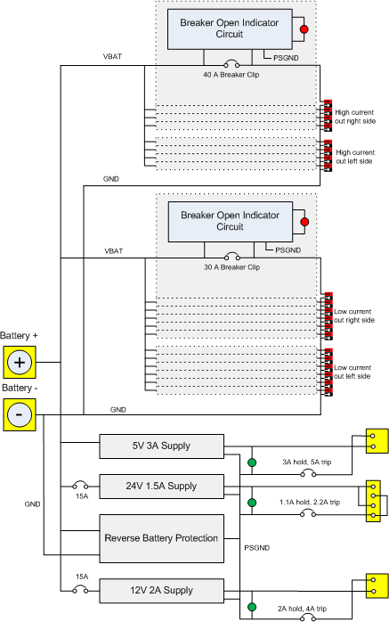
The power distribution module provides safe power for all of the robot systems, using the main 12 volt battery as its source of energy. The block diagram below shows its systems.
Starting at the top:
- The high current breakers and connectors typically provide power for motor controllers driving high loads. There are eight circuit breaker sockets, each designed for a maximum current rating of 40 Amps. There are four sets of power/ground connectors on each side of the module. Power for this system comes directly from the battery inputs of the module. Each breaker has a sensing circuit that activates an LED at the corresponding connector if there is a load connected, but the breaker is open.
- The low current breakers and connectors work exactly that same as the high current system described above, but there are twelve sets of breakers and connectors and the maximum current of a channel is 30 Amps.
- There are three DC to DC converters (switching regulators) for supplying lower current clean (low noise) power to electronic circuits on the robot. All are protected by the reverse battery protection circuit.
- The 5 volt 3 amp supply typically powers the ether-net camera. It is protected by a circuit breaker in its ground line.
- The 24 volt 1.5 amp supply is specifically designed to power the cRIO control system and has a four pin connector that matches the one on the cRIO. At its output, it is protected by a circuit breaker in its ground line. In addition, there is a 15 amp breaker on the regulator's input.
- The 12 volt 2 amp supply is typically used to provide power to the robot's WiFi router. Its design is very similar to that of the 24 volt supply. Though the output of this supply has about the same voltage as that of the battery, using power directly from the battery for electronics like the router is a bad idea because of the high frequency noise and voltage variation created by the motors and motor control circuits.
- The reverse battery protection circuit prevents current from flowing backward through the electronics in the module by disconnecting the internal ground signal from the battery if the red terminal is more negative than the black terminal.
